DRX
Instrument and Chip Handling
The easiest way to check if your flow channel is suitable for the planned experiment, is to perform a status check of the desired flow channel.
For further reading please see “What is a chip status test and how should I interpret it?”.
Chip regeneration implies that all ligand molecules immobilized on switchSENSE® electrodes in one flow channel and all potentially bound analyte molecules are completely washed off the sensor surfaces by treatment with a regeneration solution. This leaves single-stranded DNA nanolevers on the sensor electrodes, which can be re-functionalized with fresh ligand molecules by hybridization to the corresponding complementary DNA nanolevers.
The regeneration process contains two crucial steps: the denaturation of the double-stranded DNA nanolevers, leaving single-stranded DNA molecules on the electrodes and successively, the hybridization during which double-stranded nanolevers are formed again. The hybridization of the DNA nanolevers is usually monitored during a switchSENSE® experiment. Figure 10 shows typical fluorescence intensity traces corresponding to the transition of single stranded DNA nanolevers to double stranded DNA nanolevers. The basic effect that allows to observe DNA hybridization on a switchSENSE® sensor electrode is that single-stranded DNA nanolevers and double-stranded DNA nanolevers exhibit remarkably different switching properties. Due to its high flexibility, single stranded DNA can only be switched within the area above the electrode that is subjected to electric field, which extends to only a few nanometers into the electrolyte solution. In contrast to this, double stranded DNA is very rigid, with the consequence that during the repulsive switching phase, parts of the DNA nanolever that are exposed to the electric field push the major part of the nanolever far beyond the electrically affected areas. As stated previously under the Molecular Ruler principle, this translates to an increase in repulsive fluorescence intensity (Fup) and in switching amplitude, which is defined as the difference between the repulsive and attractive fluorescence intensity (ΔF).
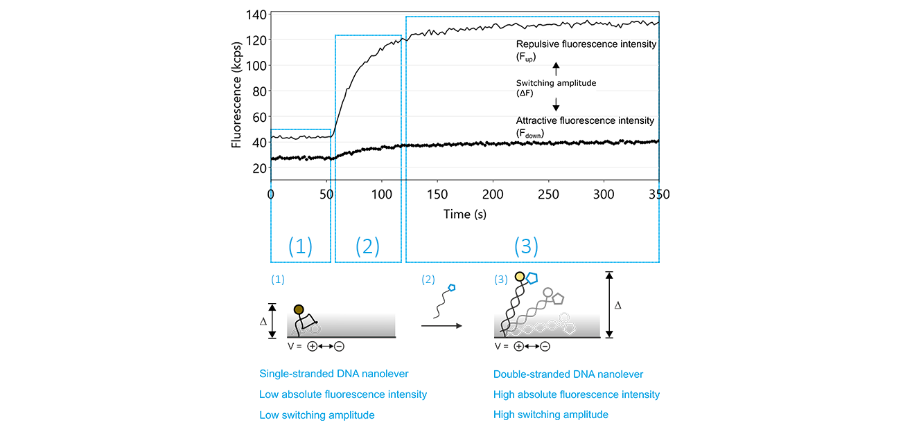
Figure 10: The denaturation of double-stranded DNA nanolevers using a regeneration solution with a basic pH value followed by re-hybridization, yielding double-stranded DNA nanolevers, are the two key features that facilitate the unique regeneration process of switchSENSE® electrodes. After denaturation, which is not recorded by the sensor system, the switching process can be monitored by observing the attractive (Fdown; dotted line) and repulsive (Fup; solid line) fluorescence intensity values. As long as the DNA nanolevers remain in the single-stranded state, the Fup is comparably low, with a reduced switching amplitude (ΔF). The hybridization of the complementary DNA is marked by a significant increase of Fup and therefore of ΔF.
Denaturation of the DNA nanolevers:
The denaturation of the double-stranded DNA nanolevers is automatically carried out by the DRX instrument by treatment of the sensor surfaces with the basic Regeneration Solution, leaving single-stranded DNA on the sensor electrodes. In case this step is not successful, the DNA nanolevers on the sensor electrodes remain double stranded, which prevents hybridization of fresh DNA-ligand conjugates. Figure 11 shows an exemplary data set of a switchSENSE® hybridization routine, during which the denaturation step was not successful. The reason for absence of denaturation or incomplete denaturation is usually shortage of regeneration solution or inactive regeneration solution. The latter is sometimes observed when the regeneration solution was stored in contact with air for an extended timescale.
How do I recognize insufficient denaturation?
- Check the absolute fluorescence intensity at the beginning of the regeneration trace. On successful denaturation, the fluorescence intensity is comparably low (Fup ~ 10 – 50 kcps). If the baseline of the hybridization trace (up to about 50 s after start of the measurement) is significantly higher, this denotes that the DNA nanolevers are still double-stranded.
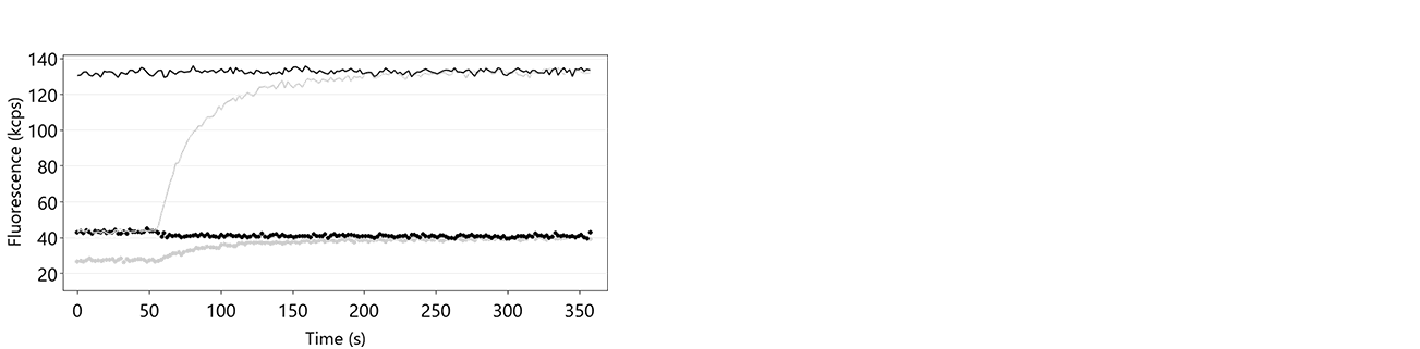
Figure 11: Fup (solid line) and Fdown (dotted line) traces of a hybridization routine after insufficient denaturation of the DNA nanolevers. It is clearly visible that Fup constantly remains at a high intensity level during the entire process, which indicates that there is no transition from single-stranded to double-stranded DNA nanolevers. In grey, the respective hybridization traces on successful denaturation are shown for comparison.
Hybridization of the DNA nanolevers:
After denaturation of the DNA nanolevers, the single-stranded DNA molecules on the sensor electrodes are re-hybridized to double-stranded DNA nanolevers by incubation with the respective complementary DNA molecules. This is a crucial step for switchSENSE® experiments, as it facilitates the immobilization of ligand molecules. Given that the denaturation step was successful, problems with the hybridization step are usually either caused by shortage of DNA solution or by incubation with non-complementary DNA molecules. Furthermore, the use of an insufficient concentration of complementary DNA will result in partial DNA nanolever hybridization. Figure 12 shows fluorescence intensity traces of three independent regeneration routines, which exhibit no or partial DNA nanolever hybridization.
How do I recognize insufficient hybridization?
- Does the fluorescence intensity increase during the hybridization? The hybridization of the complementary DNA is accompanied by a significant increase of the repulsive fluorescence intensity (Fup), caused by the transition of the immobilized DNA molecules from single-stranded to double-stranded state. On successful hybridization with bare complementary DNA, the Fup intensity should at least increase by 100 %.
- Is there a switching amplitude, i.e. is there a significant difference between Fup and Fdown? Even in single-stranded state, switching DNA nanolevers exhibit ΔF values of about 10-20 kcps. If there is no significant difference between Fup and Fdown, this points to the presence of air in the flow channel, which is usually the consequence of an empty autosampler vial.
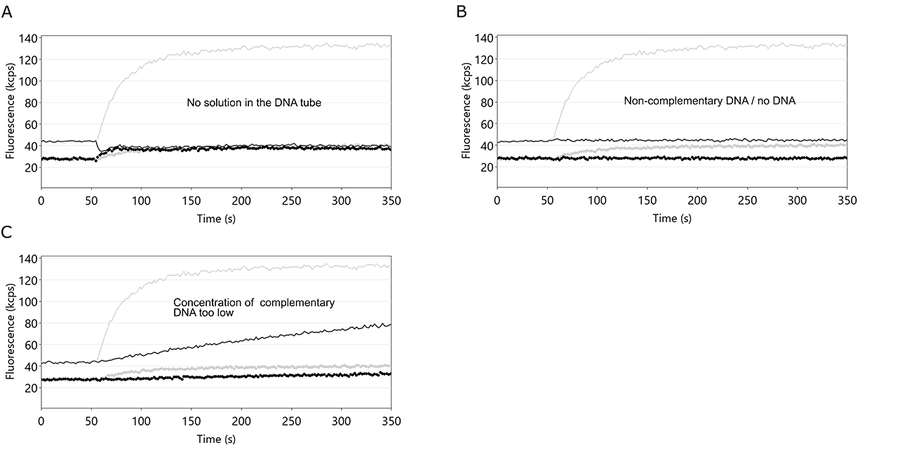
Figure 12: Fluorescence intensity profiles of switchSENSE® hybridization routines. In each example, the hybridization of the DNA nanolevers was hindered by the stated cause. A: an empty DNA vial. If the volume of the complementary DNA solution is not sufficient, air is injected into the flow channel, which immediately ceases the DNA switching motion. Fup and Fdown now show identical values. B: use of non-complementary DNA or no DNA. In both cases, the single-stranded DNA nanolevers on the switchSENSE electrodes cannot hybridize to their complementary DNA and thus remain single-stranded. In this case, Fup and Fdown remain constant. C: concentration of the applied DNA solution is too low. Corresponding to other association kinetics, the hybridization of DNA nanolevers is affected by the concentration of complementary DNA. If the concentration of complementary DNA is too low, the hybridization process is not completed within the time-scale chosen by the switchBUILD software and neither Fup, nor ΔF reach a constant final level. Grey lines depict the case of ideal DNA nanolever hybridization.
What can I do to improve the hybridization efficiency?
Typically, the concentrations of complementary DNA solutions and the corresponding hybridization times suggested by the switchBUILD software are optimized to ensure surface saturation by hybridization. Yet, in some cases, ligand molecules conjugated to the complementary DNA strand can interfere with the hybridization and thus reduce the hybridization speed. In these situations, the hybridization efficiency can be increased with the following measures:
- Increase the concentration of complementary DNA. This is a simple but efficient way to increase the hybridization speed, which scales linearly with the concentration of complementary DNA.
- Increase the hybridization temperature. Elevated temperatures generally accelerate the hybridization velocity as is the case for most biochemical reactions. Secondly, nucleic acid ligands (overhangs) that are attached to the complementary DNA can form secondary structures that hinder the formation of the double-stranded DNA nanolevers. These secondary structures can often be de-stabilized by working at higher temperatures. To perform your hybridizations at temperatures above 25 °C, activate the expert mode of switchBUILD. The desired hybridization temperature can then be adjusted in the respective experimental element. Please ensure that the ligand molecules of interest are stable at the chosen elevated hybridization temperature.
- Reduce the salt concentration of DNA conjugate solution: Similar to increased hybridization temperatures, also a reduction of salt concentration in the hybridization solution simultaneously accelerates the general DNA hybridization process and also destabilizes secondary structures of nucleic acid ligands. Please make sure to choose conditions that correspond to at least 10 mM of total monovalent salt concentration to ensure sufficient shielding of the negatively charged DNA backbone.
Briefly, the answer is yes. Decrease in the absolute fluorescence intensity is completely normal during switchSENSE® experiments. There are several factors that can affect the fluorescence emission, for instance photobleaching, chemical and thermal stress on the fluorophore, loss of DNA from the sensor surface or quenching of the fluorophore by a hybridized protein conjugate. So, do not worry about loss of fluorescence intensity between regeneration steps. When you observe an increase in the repulsive fluorescence intensity (Fup) during the respective hybridization, the sensor electrodes are successfully functionalized.
For further reading, please also refer to “What is a chip regeneration? How do I know, if my chip regeneration was successful?”.
switchSENSE® chips are very versatile, typically long-lasting and can be used for a multitude of different experiments, due to the possibility of chip regeneration. During the course of the experiments, the sensor electrodes are subjected to a certain decrease of fluorescence intensity which limits their lifespan. Furthermore, potentially harmful experimental conditions, such as high temperatures, organic solvents or extreme pH values, can negatively affect the chip viability. To ensure ideal conditions for your experiment, it is thus important to assess the quality of the sensor electrodes prior to an experiment. This is particularly advisable when a flow channel has been in use for several experimental runs. Please note that for a chip status measurement the DNA nanolevers must be in double-stranded state without attached ligand molecules. If this is not the case or if you are not sure about the state of the DNA nanolevers, please select “with regeneration” in the chip status dialog.
The chip status test is a tool that quickly provides information on the quality of all electrodes of a selected flow channel under standard conditions. After a few minutes, the tested electrodes are ranked in three categories:
- Red: Bad electrode viability. Do not use this electrode anymore!
- Yellow: Moderate electrode viability. This electrode can still be used but should be avoided for very long experiments or experiments performed under harsh conditions.
- Green: Good electrode viability.
As the lifetime of an electrode is affected by different factors, these rankings can only provide guidance for planning of your experiment. Thus, in addition to the chip status test you should always consider the following aspects:
- Under mild conditions, electrodes ranked as moderate can still be used for many experiments, including several regeneration steps.
- Electrodes used for experiments performed at a very low surface density, typically are ranked as moderate or even bad. This is expected but certainly limits the number of experiments that can be performed on such an electrode. We advise to use a fresh electrode for every low-density experiment.
- Although all electrodes inside one flow channel are exposed to identical chemical and thermal conditions, electrodes that are not actively used during experiments (i.e. not continuously illuminated) usually show a significantly less pronounced loss in fluorescence intensity.
- If you’d like to perform your experiment under harsh conditions, we advise to test these conditions under the experimental preferences that you intend to use (binding times, temperature, number of regenerations) using only one electrode of the flow channel.
switchSENSE® chips are generally robust and long-lasting, if handled and stored under recommended conditions.
Instructions for chip storage:
- Store the chip at 4 °C in its original packing, whenever it is not used for experiments.
- Do not freeze a switchSENSE® chip!
- To increase the chip life time, the DNA nanolevers should be stored in double-stranded form without attached ligand molecules. Thus, in switchBUILD add the standby routine with regeneration step at the end of your measurement. This ensures that the DNA nanolevers are hybridized with their complementary strands prior to ejecting the chip.
- The flow channels should be as dry as possible. When the chip is ejected from the DRX instrument, the used flow channels are vented with air for drying. Nevertheless, small droplets of buffer can remain in the flow channel. Therefore, it is advisable to manually purge the used flow channel with compressed gas (dust remover, nitrogen line).
- For short term storage (e.g. after an overnight measurement), the chip can remain inside the DRX instrument. Ensure to add a standby step at the end of the assay, which will purge the flow channels with air.
Instructions for chip handling:
- Always wear gloves when handling a chip to avoid contamination of the flow channels and finger prints on the glass surface.
- The chip is best handled using vacuum tweezers. Please be aware that vacuum tweezers can release the chip unexpectedly. The drop might result in damage to the chip. So please make sure to position your other hand below the chip.
- Please avoid touching the contact pads (golden squares) used for electric connection of the sensor electrodes as this might damage the DNA layers on the electrodes.
- When inserting the chip into the chip holder, make sure that the chip is in the correct orientation. This is the case, if you can read the “Dynamic Biosensors” logo on the chip.
- After extensive experiments, it is possible that the chip cannot be lifted at ease from the chip holder using vacuum tweezers. In such a situation, carefully loosen the chip by lifting it at one of the corner indentations using a clean pipette tip. Afterwards, the chip can easily be lifted with vacuum tweezers.
In rare cases, it is possible that a leak occurs in the DRX chip holder. This will not cause damage to the DRX sensor system as all ongoing measurements and fluidic steps will automatically be stopped by the switchCONTROL software. In the event of a leak during a measurement, a clear notification will pop-up in the switchCONTROL window. By following the instructions below, your DRX system will be operational again within a few minutes:
- In the switchCONTROL software: Go to „Chip“
- Select „Eject Chip Holder” and mark the flow channels that were used
- Click “Ok”
- Remove chip. As there might be liquid below the chip, the chip may adhere to the chip holder. Thus, more effort than usual might be required to remove the chip. In this case, you can carefully lift up the chip with a clean pipette tip.
- Dry the chip holder with lint-free tissues
- The liquid handling system of the DRX instrument will be re-activated only, if the leak detectors are completely dry. So, please make sure to thoroughly dry the leak detectors, which are located in the corners of the chip holder facing away from you. Purging these with compressed air or nitrogen gas is usually very efficient. Furthermore, the drying process can be accelerated by heating of the open chip holder to 50 °C for about 5 minutes. To do so, please use the manual chip temperature control function of switchCONTROL.
Both the Start and the Prime routines are default liquid handling procedures that are used to purge the DRX instrument with running buffers of interest.
The Start routine should always be performed after a Clean&Sleep routine. In this thorough purging program, the complete fluidic system, including all flow channels of the chip holder (cleaning chip is required), is rinsed with buffer to remove potential residues of the cleaning solution used previously during the Clean&Sleep routine. To run this routine, click “Fluidics”, then “Start” and follow the instructions on the screen.
The Prime routine removes all buffers from the fluidic system and refills all microtubing with fresh buffer. It is typically used between experiments to exchange the running buffer. In this case, the complete liquid handling, except for the flow channels of the chip holder, are purged. Thus, the biochip can remain inserted as buffer is not injected into the flow channels. Furthermore, the prime routine can be used to remove air from the fluidic system, for instance when the volume of buffer needed for an experiment was underestimated. To run this routine, click “Fluidics”, then “Prime” and follow the instructions on the screen.
After using a flow channel on a switchSENSE® chip (i.e. after any type of liquid has entered the flow channel), it must be vented before it can be removed from the chip holder.
This is easiest done during the chip ejection procedure:
- Go to „Chip“
- Select „Eject Chip Holder” and mark the flow channels that were used
- Click “Ok”
In some cases, you might want to vent a flow channel that was used but continue experiments on another flow channel without the need to eject the chip holder. This can be done with the following switchCONTROL functions:
- Go to “Fluidics”
- Select “Maintenance”
- Select “Vent channels” to select a specific channel
The selected microfluidic channels will be purged with air.
All DRX instruments can be equipped with different autosampler adaptors (standard tray, 96-well plate tray).
To change the autosampler tray, please refer to the DRX manual or contact the Dynamic Biosensors support team at support@dynamic-biosensors.com.
After exchange of the autosampler tray, it is mandatory to adjust switchCONTROL and switchBUILD accordingly:
switchCONTROL:
- Go to “File”
- Select “Options” and “Autosampler”
- Select the correct format
- Restart with switchCONTROL
switchBUILD:
- Go to “Settings”
- Select “Autosampler”
- Select to correct format
- Eject the chip holder (without channel venting) and check if the chip was placed correctly in the chip holder. The chip was inserted correctly if you can easily read the “Dynamic Biosensors” label.
- Make sure to close the chip holder properly. This is the case, if you hear two clicks caused by the locking mechanism.
- Retract the chip holder again and check if alignment works.
During alignment, check if you can see the alignment crosses in the electrode display located in the upper left corner of the switchCONTROL window. If this panel stays constantly black during alignment, there might be a connection problem between computer and DRX instrument. In such a case, follow the re-start instructions:
- Close the switchCONTROL software
- Turn off computer
- Shut down the DRX instrument
- Wait for about 30 seconds
- Turn the instrument back on
- Start computer and open the switchCONTROL software
- Go to “Chip”
- Select “Align”
In case the chip alignment is still not successful after following these instructions, please contact the Dynamic Biosensors support team at support@dynamic-biosensors.com
You can only observe an experiment in one flow channel at a time. Nevertheless, you can run subsequent experiments in all the channels: consecutive experiments can be set up for the different channels in the switchBUILD software by inserting a “new channel” element into the taskflow. The DRX will automatically use the flow channels in the preset order.